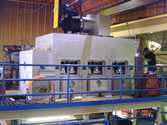
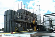
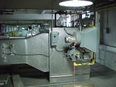
The following is a recent case study of an impingement dryer done for a customer, with the intent to improve their dryer's performance.
Dryer Description
The dryer is a two-zone, arched impingement dryer, sixty feet in length. Each zone is of equal length, thirty feet. The web is supported by idler rolls on twenty-four-inch horizontal centers. The average web wrap on each roll is 1.34 degrees. The web path, over rolls in an arch, provides an effective dryer length in each zone of approximately 29.625 feet, 59.25 total feet. From the entry and exit rolls to the web entry and exit slots, the web passes through an approximately additional three feet.
Direct impingement nozzles are mounted above the web at nine-inch spacing. Each nozzle is 104 inches wide. Nozzle slot widths vary dramatically, with a substantial number of nozzles damaged, so the slots may vary wider and narrower than the original design. As best as I could measure, the original slot width was probably around 0.05-0.07 inches.
The nozzles are fed by a central header, thirty-four inches wide. This results in a nozzle cantilever length, to each side of the central header, of thirty-five inches. The concept of a central header with cantilevered nozzles, as designed, is preferred, because this allow the impingement air leaving the web to pass through the nozzles. This is done to minimize the recirculated and exhaust air from being drawn across the web to the edge of the web and over-drying the edges of the web.
A problem with this dryer is that the nozzle design does not properly distribute the supply air across the profile of the web. Measured nozzle velocities are provided in the attached Nozzle Velocity Spreadsheet.
Measurements Discussion
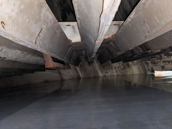
As can be seen from the spreadsheet, the velocities of the nozzles are consistently higher at the center of the web as compared to the outer ends. This will result in the center of the web being dried at a higher rate than the edges. As can be seen in the photo below, this was addressed by blocking off the center of several nozzles in the web path.
From the spreadsheet you can also see calculations of the internal velocities of the supply air through the length of the nozzles. Best practices recommends that the velocities through the nozzle to be less than seven percent of the nozzle slot velocity. With the slot velocity averaging around 3500 fpm, the velocity through the nozzle where it is fed by the central plenum, should not exceed around 245 fpm. With the nozzle cantilever of thirty-five inches, the nozzle slot width averaging 0.06 inches, and the nozzle velocity around 3300 fpm, the air supplied to the cantilever is around 48 cfm. The cross area of the nozzle is approximately 0.09 ft2. The volume, 48 cfm, divided by the cross-sectional area of 0.09 ft2, yields a velocity of 533 fpm, dramatically higher than the recommended 245 fpm. The nozzle design is the cause of the uneven drying across the profile of the web. The nozzle should have a minimum cross-sectional area of 0.21 ft2, or 30 in2.
This would be a five inch by six inch or similar rectangular configuration.
Without changing the nozzles, the greatest factor affecting your effective drying capability is the length of the impingement air throw from the nozzles, measured by the distance between the nozzles and the web. The current dryer setup is a detriment to achieving the maximum drying capability. First, it is set up backwards. Usually, you try to have the first zone of the dryer with less aggressive drying, to be followed up by more aggressive drying in the second zone. Your current setup is opposite. The nozzles in the first zone are closer to the web than in the second zone. Additionally, the nozzles are far too distant from the web to provide maximum drying performance.
In Zone 1 the nozzles ranged from 2 ½ inches to 5 ½ inches. The closer dimensions were at the entry side to the zone. Once again this is opposite of what should be set up. In Zone 2 the nozzles ranged from 9 ½ inches near the exit end of the dryer to as low as 3 ½ inches at the entry to Zone 2, opposite of recommended design and significantly farther from the web than advisable. The drying capability of the dryer is significantly degraded by the nozzle set up.
We calculate an effective heat transfer rate, as currently setup, in Zone 1, of approximately 9.8 Btu/hr/ft2/D°F. The calculated heat transfer rate for Zone 2, as currently setup, is approximately 6 Btu/hr/ft2/D°F. This yields a dryer effective drying heat transfer rate of approximately 7.9 Btu/hr/ft2/D°F. Checking the 180 fpm product data, we do see a heat transfer rate required to be around 7 Btu/hr/ft2/D°F, which does correlate to the effective rate of the dryer as set up during my inspection.
Exhaust rates for the two zones were measured at 1,696 acfm at 133°F (1516 scfm) for Zone 1 and 1,711acfm at 128°F (1542scfm) for Zone 2.
We measured the make-up air entering your dryer at the entrance and exit web slots. These are not exact numbers, as the velocity of the air entering the dryer at each slot varied significantly. Our best estimate is that approximately 1,500 to 2,000 cfm enters your dryer through the slots. This leaves approximately 1,000 to 1,500 cfm being supplied as make-up air directly to the burner boxes through the openings in the recirculation ductwork to the room.
Recommendations
- Replace the nozzles with properly designed nozzles. This would require a significant capital expenditure.
- Locate the nozzles an appropriate distance from the web and do not allow them to be moved. Our recommendation, as a starting point, would be for Zone 1 to be located two inches from the web, and in Zone 2 the nozzles to be located one inch from the web. These should be fine tuned through experimentation and then never moved after the best distance is determined.
- Use the variable frequency drives on the supply air fans for the two zones to vary the effective drying rate for different coating weights. This will allow you to vary the nozzle velocity impinging on the web, a far more repeatable variable than varying the distance that the nozzles are from the web. Varying the velocity will enable you to match the dryer performance to a range of products run. We envision you will have a menu of velocities for light and heavier weight coatings.
- Once the dryer setup is corrected, we recommend that you experiment with running higher web speeds and higher supply air temperatures. We would expect that you can operate at higher temperatures if the web speeds are increased. You can use the web exit temperature to help determine the optimum web speeds, nozzle velocities and supply air temperatures for your various products.
