New Burner Box Systems Delivered

Burner Box Systems for a New Direct Impingement Dryer

Recently we delivered these two burner box systems for a new two zone, fifty-foot direct impingement dryer we are supplying.  Each burner box system features a 1.5 MMBtu/hr. Maxon Ovenpak natural gas burner, piped, and wired prior to shipping.  A Chicago Blower recirculating fan is incorporated into the burner system and the controls are coordinated with the line control system through Allen Bradley remote I/O modules.

 picmonkey_image.jpg 

The description of the impingement dryer will be featured in a future news article.

Teflon Sintering Ovens

Teflon-coated and sintered films and fabrics are cost effective insulators used in the emerging energy fields.  Cire Technologies, Inc. is excited to announce a new equipment emphasis to help meet the high demand for coating and sintering Teflon on web materials.  For the industry, we have successfully provided horizontal and vertical ovens for Teflon drying and sintering on both films and fabrics.  We are experienced in designing high-temperature flotation dryers and ovens, with an emphasis on energy recovery.

Characteristics of our units include the following:

  • Flotation design resulting in no contact with the web through the oven.
  • Vertical or horizontal orientation.
  • Multiple temperature and velocity zones.
  • Electric or gas-fired designs available. Indirect gas-fired heating is also available.
  • Uniform temperature and velocity profiles across the web.
  • Operating temperatures up to 400°
  • Significant energy recovery, utilizing the heat content of the exhaust air to pre-heat the make-up air used in the oven.
  • Planer retraction or access door with no retraction designs.
  • Designed to compensate for thermal expansion of the nozzles, headers, and corresponding ductwork. Thermal stresses are limited, ensuring a long life to the oven.
  • Custom designed to your application.

Contact us for a consultation on your application.  We look forward to demonstrating our capabilities.

Impingement Dryer Case Study

The following is a recent case study of an impingement dryer done for a customer, with the intent to improve their dryer's performance.

Dryer Description

The dryer is a two-zone, arched impingement dryer, sixty feet in length.  Each zone is of equal length, thirty feet.  The web is supported by idler rolls on twenty-four-inch horizontal centers.  The average web wrap on each roll is 1.34 degrees.  The web path, over rolls in an arch, provides an effective dryer length in each zone of approximately 29.625 feet, 59.25 total feet.  From the entry and exit rolls to the web entry and exit slots, the web passes through an approximately additional three feet.

Direct impingement nozzles are mounted above the web at nine-inch spacing.  Each nozzle is 104 inches wide.  Nozzle slot widths vary dramatically, with a substantial number of nozzles damaged, so the slots may vary wider and narrower than the original design.  As best as I could measure, the original slot width was probably around 0.05-0.07 inches.

The nozzles are fed by a central header, thirty-four inches wide.  This results in a nozzle cantilever length, to each side of the central header, of thirty-five inches.  The concept of a central header with cantilevered nozzles, as designed, is preferred, because this allow the impingement air leaving the web to pass through the nozzles.  This is done to minimize the recirculated and exhaust air from being drawn across the web to the edge of the web and over-drying the edges of the web.

A problem with this dryer is that the nozzle design does not properly distribute the supply air across the profile of the web.  Measured nozzle velocities are provided in the attached Nozzle Velocity Spreadsheet.

Measurements Discussion

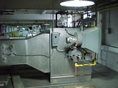
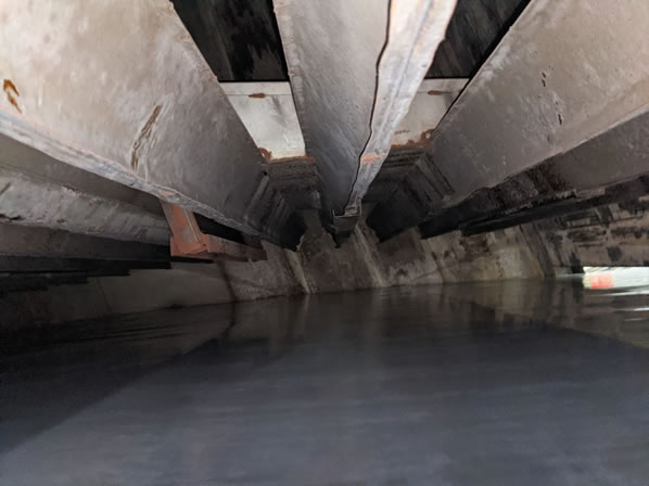
As can be seen from the spreadsheet, the velocities of the nozzles are consistently higher at the center of the web as compared to the outer ends.  This will result in the center of the web being dried at a higher rate than the edges.  As can be seen in the photo below, this was addressed by blocking off the center of several nozzles in the web path.

Dryer case study

From the spreadsheet you can also see calculations of the internal velocities of the supply air through the length of the nozzles.  Best practices recommends that the velocities through the nozzle to be less than seven percent of the nozzle slot velocity.  With the slot velocity averaging around 3500 fpm, the velocity through the nozzle where it is fed by the central plenum, should not exceed around 245 fpm.  With the nozzle cantilever of thirty-five inches, the nozzle slot width averaging 0.06 inches, and the nozzle velocity around 3300 fpm, the air supplied to the cantilever is around 48 cfm.  The cross area of the nozzle is approximately 0.09 ft2.  The volume, 48 cfm, divided by the cross-sectional area of 0.09 ft2, yields a velocity of 533 fpm, dramatically higher than the recommended 245 fpm.  The nozzle design is the cause of the uneven drying across the profile of the web.  The nozzle should have a minimum cross-sectional area of 0.21 ft2, or 30 in2.

This would be a five inch by six inch or similar rectangular configuration.

Without changing the nozzles, the greatest factor affecting your effective drying capability is the length of the impingement air throw from the nozzles, measured by the distance between the nozzles and the web.  The current dryer setup is a detriment to achieving the maximum drying capability.  First, it is set up backwards.  Usually, you try to have the first zone of the dryer with less aggressive drying, to be followed up by more aggressive drying in the second zone.  Your current setup is opposite.  The nozzles in the first zone are closer to the web than in the second zone.  Additionally, the nozzles are far too distant from the web to provide maximum drying performance.

In Zone 1 the nozzles ranged from 2 ½ inches to 5 ½ inches.  The closer dimensions were at the entry side to the zone.  Once again this is opposite of what should be set up.  In Zone 2 the nozzles ranged from 9 ½ inches near the exit end of the dryer to as low as 3 ½ inches at the entry to Zone 2, opposite of recommended design and significantly farther from the web than advisable.  The drying capability of the dryer is significantly degraded by the nozzle set up.

We calculate an effective heat transfer rate, as currently setup, in Zone 1, of approximately 9.8 Btu/hr/ft2/D°F.  The calculated heat transfer rate for Zone 2, as currently setup, is approximately 6 Btu/hr/ft2/D°F.  This yields a dryer effective drying heat transfer rate of approximately 7.9 Btu/hr/ft2/D°F.  Checking the 180 fpm product data, we do see a heat transfer rate required to be around 7 Btu/hr/ft2/D°F, which does correlate to the effective rate of the dryer as set up during my inspection.

Exhaust rates for the two zones were measured at 1,696 acfm at 133°F (1516 scfm) for Zone 1 and 1,711acfm at 128°F (1542scfm) for Zone 2.

We measured the make-up air entering your dryer at the entrance and exit web slots.  These are not exact numbers, as the velocity of the air entering the dryer at each slot varied significantly.  Our best estimate is that approximately 1,500 to 2,000 cfm enters your dryer through the slots.  This leaves approximately 1,000 to 1,500 cfm being supplied as make-up air directly to the burner boxes through the openings in the recirculation ductwork to the room.

Recommendations

  • Replace the nozzles with properly designed nozzles. This would require a significant capital expenditure.
  • Locate the nozzles an appropriate distance from the web and do not allow them to be moved. Our recommendation, as a starting point, would be for Zone 1 to be located two inches from the web, and in Zone 2 the nozzles to be located one inch from the web. These should be fine tuned through experimentation and then never moved after the best distance is determined.
  • Use the variable frequency drives on the supply air fans for the two zones to vary the effective drying rate for different coating weights. This will allow you to vary the nozzle velocity impinging on the web, a far more repeatable variable than varying the distance that the nozzles are from the web. Varying the velocity will enable you to match the dryer performance to a range of products run.  We envision you will have a menu of velocities for light and heavier weight coatings.
  • Once the dryer setup is corrected, we recommend that you experiment with running higher web speeds and higher supply air temperatures. We would expect that you can operate at higher temperatures if the web speeds are increased. You can use the web exit temperature to help determine the optimum web speeds, nozzle velocities and supply air temperatures for your various products.

New Solvent Evaporating Batch Oven

Cire Technologies, Inc. has successfully designed, fabricated and started-up a new custom batch oven for a Massachusetts customer. The oven was delivered completely assembled, requiring very little installation cost.

 ink oven ready to ship

 Figure 1 – Batch Oven Ready to Ship

The batch oven is designed to evaporate solvents from ink solids. Characteristics of the oven include:

  • A vertical configuration to fit into the customer’s limited floor space. The original design was for a horizontal configuration, but as the customer determined that space was limited, we were able to modify the design to a vertical unit to accommodate our customer’s needs.
  • Design operating temperature of 300°F, with capability to operate up to 400°
  • Class 1, Division 2 electric design.
  • Electric heat with 30 kW of electric coils mounted in the recirculating air stream.
  • A supply/recirculating fan and exhaust fan are integrated into the oven assembly. Both fans are spark resistant and include EXP rated motors.
  • A Watlow controller, including ramp control, regulates the oven temperature. The controller utilizes a modulated SCR for tight temperature control.
  • Fully aluminized steel construction, with four-inch insulated walls, to keep the exterior of the oven cool. Use of perforated metal between wall skins eliminates the potential of exterior skin hot spots.
  • A Mine Safety LFL monitor to assure safe solvent concentration levels in the oven.
  • Coil sheath temperature monitoring to keep the coil sheath temperatures below the lowest auto-ignition temperature of the solvents used. These are an added safety we provided for use by the customer until safe operating parameters for the oven are established. Though LFLs should be within safe limits to allow hotter coil sheath temperatures, we felt it prudent to provide this additional safety until the customer established procedures to ensure the oven operated well within those limits.
  • The oven was supplied with a complete control system, including Allen Bradley variable speed drives on both fans, that enable the process to be optimally tuned.
  • A batch timer allows the batch to shut down without operators present.

For more information on how Cire Technologies, Inc. can build a custom dryer for you, please click the Quick Connect on the left or complete the Request Info Form found HERE.

New Thermal Oxidizer and Batch Oven

Cire Technologies, Inc. proudly provided a Connecticut customer with an integrated batch oven and thermal oxidizer system.  We purchased the batch oven and integrated our thermal oxidizer to provide a complete system to our customer.

oven oxidizer installed Cire

The thermal oxidizer is used by the customer in a burn-off mode to eliminate odor and smoke.  For the balance of the customer’s process, the oxidizer fan exhausts the oven without the burner operating.

Our oxidizer was designed to be supported above the oven.  It was fully assembled on the support frame including all gas train and control components, to make the oxidizer fully operational.  Installation was therefore extremely simple, with the oxidizer assembly set on the oven, supported by independent legs.

The inlet duct for the oxidizer sits on top of the oven exhaust duct, and is designed to handle oven temperatures up to 1200°F.  The thermal oxidizer is an afterburner, with no heat recovery, with exhaust temperatures up to 1400°F.  To handle the high oven and oxidizer temperatures, dilution air is introduced to the exhaust stream prior to the exhaust fan.  The fan therefore will not see temperatures above 300°F, reducing the cost and maintenance of the fan.

This oxidizer system includes a Maxon Corporation, Kinemax, natural gas nozzle burner.  The burner setup includes a combustion air fan and a Maxon Corporation Micro-Ratio valve to control the natural gas and combustion air flows.

View Burner Assembly Cire

Simplifying the installation, complete gas and combustion air trains and the oxidizer controls, were incorporated with the oxidizer skid.  The gas train and control system utilize Honeywell flame safeguard and gas train components.  The control systems for the oven and oxidizer are integrated, so that full control of the system is accessible from the oven control panel.

The entire project from design to completed installation and commissioning was completed on time and on budget.

For more information on how Cire Technologies, Inc. can work with you to update or repurpose existing equipment, please click the Quick Connect button on this page or go to Request Info (click) page.

Integrated Oxidizer Gas Combustion Controls Cire

Cire Latest Blogs

Eric Becht
02 May 2014
Projects
At Cire Technologies we are very cognizant of our customers’ cost of operating our equipment. One area we excel at is reusing waste heat from our equipment back into the process. A current project ill...
4
Eric Becht
14 April 2014
Dryer Design
A Sample Dryer Project In this our last post on impingement dryer design we illustrate a simple set of dryer design calculations. Given: Tweb entry=60°FTweb exit=135°FTAir=220°F, TWeb=120°F or the wet...
2
Eric Becht
31 March 2014
Dryer Design
The Primary Components of an Impingement Dryer – Part 2 In this post we continue and finish the discussion of the primary components of an impingement dryer. Impingement Nozzles and Supply Plenums The...
2
Contact Us

logo-contactPlease complete the form below to contact us. 
We will respond within 24 hours to all requests.

251 Boulevard • Mountain Lakes, NJ 07046-1209
800-388-8301 • 973-402-8301 • Fax: 973-402-8302
1000 characters left